


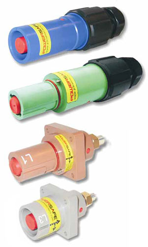
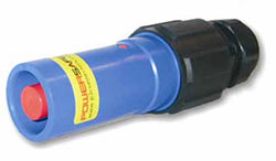
The Powersafe connector series is based on a standard format for mechanically keyed and locked high current single pole connectors, as utilised by the UK and European temporary power industries. This connector format was first introduced in 1993 by Litton Veam and was quickly adopted by the leading Generator Power companies, Utility companies, and the Entertainment Industry. These types of connector have now been employed in many other applications, such as Military field power, Shipboard power, Railway vehicles, Dock side power, Building installations and Switchgear. Powersafe was designed by principal members of the original engineering team, who had developed this format of connector, and have been integrally linked with the subsequent development of these types of products over the last decade. Our extensive knowledge of electrical power connector design, the applications and customer requirements, specific to this type of connector, is probably unsurpassed by no other manufacturer in the world.
Raising the Bar
Although Powersafe connectors are still fully intermateable with the original, a redesign of the active contact element and material compositions has up-rated the current carrying capacity and the short circuit ratings of the connector to meet current customer demands. This makes Powersafe the highest current rated connector system of its type on the market.
New Features
- Increased Current Carrying Capacity
- Increased Surge Current Rating
- Increased Short Circuit Ratings
- Increased Ingress Protection Rating
- Reduced Insertion force
- Improved cable strain relief
- Improved Impact resistance
- High Temperature Resistant Materials
- Panel Mount Connector - Mounting Plates
- Rubber Hand Grip for ease of coupling and added impact protection.
- Rubber Protective Caps to protect connectors from moisture, dirt and abrasion, when uncoupled.
- RoHs Compliant
Standard Features
- Colour Coded
- Mechanically Keyed to prevent connection errors
- Flame Retardant UL94-VO
- Locking mechanism to prevent accidental disconnection under load
- Finger Proof contacts both genders (IP2X) to prevent access to electrical contacts when uncoupled
- Screw and Crimp terminals to facilitate cables from 25mm² - 300mm² CSA
- Multipoint, self wiping contact area
- Silver Plated Contacts
- Permanent Identification marking
- High Impact bodies
- Integral cable strain relief
- Metric EN compliant cable glands, with increased cable clamping range
- No special tools required for assembly
- Daisy Chain Hook Up system
- CE Compliant
Increased Electrical Performance
The quality of an electrical contact is dependent upon its electrical and mechanical properties. Ragnar Holm's renowned work on the principles of electrical contact performance showed that no contact system transmits current over its entire surface, but at particular contact points. With flat surface contacts the number of connections points is unknown, however with a multipoint system it can be assumed there will be one per bridge, and a more reliable low resistance contact path can be attained. The higher the resistance in the electrical contact, the higher the temperature rise at the connection will be. As Power loss and temperature rise in the connector are directly proportional to the contact resistance, a low resistance current path will minimise Power loss. For this reason most power connector designs utilise some form of multi contact connection point to attain a low resistance path. This is an important consideration in design of Power electrical contacts, as excessive temperatures within the connector will affect other protective devices within the electrical circuit, and will lead to premature deterioration of the electrical contact. This in extreme cases could potentially lead to circuit failure. There are for this reason many National and International specifications and regulations which detail allowable temperature rise within connectors and or specific equipments. The Powersafe connector was designed to comply with the requirements of these specifications at its full rated current.
Current Carrying Capacity
The traditional active element of the contact design used in this type of connector, consists of multilam torsion spring band, which consists of 23 spring loaded louvers rated at 28amps each, which gives a total current carrying potential of 644amps (23 louvers x 28A = 644A) When higher currents (more than 644A) are applied to this design, the bands integrity can be compromised and excessive temperature rise results in power loss and circuit integrity issues. In addition the long term performance of the contact will be substantially reduced. The Powersafe system uses an improved design which comprises of 29 current transfer bridges rated at 30amps each which gives a total current carrying potential of 870amps (29 bridges x 30A = 870A) Therefore there is no contact degradation and the lower temperature rise attained at maximum rated current means, improved performance and increased safety. Short Circuit Current This is a function of the connector's ability to withstand short time fault currents, without failure, thereby enabling the circuit protective devices to operate safely. The shorter the path travelled by the current through the current bridge, the greater the short time current which can be transmitted. Following requests from customers, specifiers and installers for product compliant to their requirements and to address potential liability and safety issues, the geometric design of the band optimises the current bridge to give an increase in short circuit ratings. Typical short circuit rating requirements are defined within
- The UK Electricity "LV Distribution Fuse Board specification" ESI 37-2
- The UK "Codes of Practice for Design and installation of temporary distribution systems delivering a.c electrical supplies for lighting, technical services and other entertainment related purposes" (BS7909)
Powersafe Band Technology
The contact band is the active element of the design which transfers current through the connection. It consists of a series of sprung current-transfer bridges that give the following benefits.
- Low contact resistance
- Low voltage drop
- High short circuit currents
- Compact design
- Self cleaning
- Low insertion force
- High current transfer density
- High number mating cycles
- Large working range
 The band is a strip-form, sprung contact element which is inserted between two conducting surfaces to transfer current. The Band consists of a series of contact bridges that provide reliable, low loss, current transfer. The contact band also has a high short-circuit rating through its compact dimensions. The band is inserted in a dovetail recess for positive location and to assure mechanical stability.
Special Features
Due to its specially designed geometry and manufacture, an ideal ratio of the grid spacing to the width of the current bridges has been achieved. For a bridge length of 3mm the grid spacing is only 2mm, resulting in a high bridge density. The current bridges are therefore 50% longer than the grid spacing.  This has the following advantages: 1) Higher Current Carrying Capacity 2) Due to a larger number of current bridges per unit length, resulting from the low grid spacing of 2mm. 3) Large Tolerance Compensation 4) Due to the relatively large spring working range resulting from the 3mm length of the current bridges. The contact force is very low in relation to the impressive current carrying capacity of the individual current bridges. This results in low insertion and withdrawal forces, a particular advantage for high current connectors. In addition, the current bridges are arranged at an angle to the axis of insertion. This reduces wear and score marking and increases the working life of the contact.
 Design
The Band carries a large number of current bridges (S), each of which is joined to the supporting edge strips (D) through two torsion arms (C). The current paths are defined by three contact lines to the conducting surfaces. Each bridge has one dynamic (A) and two static (B) contact lines. A single dynamic line makes electrical contact with the moving part of the contacts, while two static lines ensure contact with the locating recess. The Band is manufactured in high grade beryllium copper alloy (CuBe2) by punching, lancing and bending. After the formed band has been hardened, it is silver plated. The current bridge represents an independent spring which is additionally spring-loaded by the two torsion arms. Each individual bridge is thus self-sufficient in providing the contact force required for current transfer. The current bridges are connected to each other at both sides by the edge strips this also gives mechanical stability to the band. The strip edging locates the contact band securely in its recess.
Rated Current
The current rating of the Powersafe connector is up to 800amps continuous. A key element in determining the current carrying capacity of the connector and cable configuration is the type and cross sectional area of the cable being used. Figure 3 show typical values taken from IEE wiring Regulation BS7671 Table 4E1A reference method 12, cable in Free Air. The values relate to single core, copper stranded cable with Rubber Insulation with an operating temperature of 90° C. For Cables types with operating temperatures of less than 90 °C the current ratings will be reduced.
Product Technical Overview
- See Ratings above
- Double Allen Screw Terminals are standard for cables up to 150mm CSA (500amp Maximum Continuous rating). Crimp terminals are standard for larger cable sections up to 300mm CSA (800amp Maximum Continuous rating).
- In accordance with EN 60529 when mated Powersafe meets the requirements of IP68.
- In the unmated position both source and drain connectors as IP2X rated.
| No. of Contacts | 1 |
| (a) Maximum Continuous Current Rating | Up to 800A |
| Surge Current | 75kA |
| Short Circuit Rating | Up to 35.5kA |
| Cable Cross Sectional Area C.S.A | 25mm²- -300mm² |
| (b) Contact Termination | Screw or Crimp |
| Mating Method | Bayonet Lock |
| Operating Voltage | 1000Vac |
| Max Rated Voltage to Earth | 2KVac/3KVdc |
| Minimum Flashover | 9.5KVdc or AC Peak |
| Insulation Resistance | >5M ohms @500Vdc |
| (d)Ingress Protection | IP68 |
| Protection against electric shock | IP2X |
| Flammability | UL94-VO |
| Mating cycles | >500 |
| Shell Material | High Temperature Thermoplastic |
| Contact Plating | Silver |
Powersafe Part Number Configurator / Ordering Codes for Complete Connectors
| Type | Key Position | Colour | Contact Type | Cable Grip Clamping Range |
| SLS | E | GN | S120 | 40A |
| SLS = Line Source | E= Earth | GN = Green | S120 = 120mm² Set screw | 40B = 22-32mm |
| SLD= Line Drain | N= Neutral | BL = Blue | C300 = 300mm² Crimp | 40A= 19-28mm |
| SPS = Panel Source | 1 = Line 1 | BN = Brown | C240 = 240mm² crimp | 40S = 15=23mm |
| SPD = Panel Drain | 2 = Line 2 | BK = Black | C185 = 185mm² crimp | |
| |
3 = Line 3 | GY = Grey | C150 = 150mm² crimp | |
| |
|
R = Red | C120 = 120mm² crimp | |
| |
|
Y = Yellow | C95 = 95mm² Crimp | |
| |
|
W = White | C70 = 70mm² Crimp | |
| |
|
|
C50 = 50mm² crimp | |
| |
|
|
C35 = 35mm² Crimp | |
| |
|
|
C25 = 25mm² Crimp | |
| |
|
|
T5 = 500A threaded post | |
| |
|
|
T8 = 800A threaded Post | |
Component Parts
- Secondary Lock Release Key
- R95 Reduction Sleeve for Screw terminal Contact
- R70 Reduction Sleeve Kit for Screw terminal Contacts
- R50 Reduction Sleeve Kit for Screw terminal Contacts
- R35 Reduction Sleeve Kit for Screw terminal Contacts
- R25 Reduction Sleeve Kit for Screw terminal Contacts
- Protective Rubber Dustcap for Line Drain
- Protective Rubber Dustcap for Line Source
- Protective Rubber Dustcap for Panel Drain
- Protective Rubber Dustcap for Panel Source
- IP Environmental Locking Dustcap for Line Source*
- IP Environmental Locking Dustcap for Line Drain*
- IP Environmental Locking Dustcap for Panel Source*
- IP Environmental Locking Dustcap for Panel Drain*
- Rubber Hand Grip for Line Drain or Line Source
- Dowel Pin for Line Source
- Panel Mounting Nut Plate for Panel Source and Panel Drain
- Dowel Pin for Line Drain
- Dowel Pin for Panel Source or Panel Drain
- Cable Gland for 22-32mm cable diameters (40B)
- Cable Gland for 19-28mm cable diameters (40A)
- Cable Gland for 15-23mm cable diameters (40S)
- Insulator Kit Line Source Earth Green**
- Insulator Kit Line Source Neutral Blue**
- Insulator Kit Line Source Line 1 Brown**
- Insulator Kit Line Source Line 2 Black**
- Insulator Kit Line Source Line 3 Grey**
- Insulator Kit Line Source Neutral Black**
- Insulator Kit Line Source Line 1 Red**
- Insulator Kit Line Source Line 2 Yellow**
- Insulator Kit Line Source Line 2 White**
- Insulator Kit Line Source Line 3 Blue**
- Insulator Kit Line Drain Earth Green**
- Insulator Kit Line Drain Neutral Blue**
- Insulator Kit Line Drain Line 1 Brown**
- Insulator Kit Line Drain Line 2 Black**
- Insulator Kit Line Drain Line 3 Grey**
- Insulator Kit Line Drain Neutral Black**
- Insulator Kit Line Drain Line 1 Red**
- Insulator Kit Line Drain Line 2 Yellow**
- Insulator Kit Line Drain Line 2 White**
- Insulator Kit Line Drain Line 3 Blue**
- S120 Contact Kit for Line Source***
- S120 Contact Kit for Line Drain***
- C240 Contact for Line Source
- C240 Contact for Line Drain
* For IP Environmental Locking Dustcap, specify Key and Colour e.g.SCP0100-E-GN.
** Insulator Kits consist of a complete marked and labeled insulator, with Dowel Pin. (Excludes cable gland and contact which can be ordered separately)
*** S120 Contact kit consists of complete contact assembly for 120mm sq cable section and includes R120 Sleeve.