


Prysmian Rondoflex (C)-FC (N)GRDGCGOEU-J Cable
Overall Screened Festoon Cable for FC-Drives
For use on festoon systems, e.g. on gantry cranes, hall gantry cranes, rack material handling equipment, transportation systems or machine tools.Especially where some danger of interference of data cables produced by power cables can be expected or max. emission values acc. to EN 55011/55022 must be achieved. The cables are used for high mechanical stresses and frequent bending. Also suitable for use as a flexible motor power supply cable.
Electrical Specifications
| Rated voltage | Uo/U = 0.6/1 kV |
| Max. permissible operating voltage in AC systems | U max (eff) = 1.2 kV |
| AC test voltage | 5 kV, 5 min |
| max. permissible peak AC voltage | U^= 2.4 kV |
| For connection on frequency converter | U max = 690V |
| Current-carrying capacity | According to DIN VDE 0298, Part 4 |
| EMV | EMV |
| Standards | Based on DIN VDE 0250, Part 814 VDE Reg. No. 7841; GOST R |
Thermal Specifications
| Ambient temperature | |
| -Fully flexible operation | -35°C to +80°C |
| -Fixed installation | -50°C to +80°C |
| Max. permissible operating temperature of the conductor | 90°C |
| Short-circuit temperature of the conductor | 250°C |
Mechanical Specifications
| Tensile load | Up to 15 N/mm² |
| Torsional stresses | No application |
| Minimum bending radii | According to DIN VDE 0298, Part 3 |
| Travel speed | |
| -Trolley | Guidance value: up to 240m/min Note: The trouble free operation is influence by a number of factors (e.g.space, cable weight, loop length, number of motor driven carriers).It is recommended to consult the cable manufacturer at travel speeds beyond 240 m/min. |
| Additional tests | Bending test |
Chemical Specifications
| Resistance to Oil: | DIN VDE 0473, Part 811-2-1, Para. 10 |
| Weather resistance: | Unrestricted use outdoors and indoors, resistant to ozone, UV and moisture |
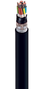
Design Specifications
| Conductor | Finely stranded copper conductor (bare electrolytic copper), class 5 |
| Earth conductor | Tinned, extremely finely stranded copper conductor, class FS |
| Insulation (refer also to DINVDE 0207) | PROTOLON, basic material EPR, rubber compound 3GI3 |
| Core identification | black, blue, brown, earth conductor green-yellow |
| Core arrangement | up to 10²mm: 4-core design from 16mm² on: Three main conductors, earth conductor splitted into three parts and placed into the interstices |
| Inner sheath | Basic material EPR, compound type GM1b, color: black |
| Overall shield | Braid screen made of tinned copper wires, surface covered: >80%,transfer impedance <100mOhm/m at <= 30MHz |
| Outer sheath | Basic material PCP, rubber compound 5GM3, colour: black |
| Marking | RONDOFLEX (C)-FC (N)GRDGCGÖU-J (number of cores)x(cross section) 0,1/1 kV VDE-Reg.-No. 7841 |
| Remark at short circuit | Caused by external damages a short circuit current can occur between phase conductor andthe screen or between a phase conductor and a protective conductor. In these cases only thecross section of the screen or the cross section of on protective conductor is available to carrythe fault current. The effective resistance of the screen or protective conductor is given by thedistance between the point of the fault and the ground connection! |
Prysmian Rondoflex (C)-FC (N)GRDGCGOEU-J Ordering Information
| No. of cores and nominal cross-section |
Order No. | electr. Shield cross-section | Conductor diameter | Overall diameter of cable Min. value |
Overall diameter of cable Max. value |
Approx. net weight for 1000 m | Max. permissible tensile force |
| mm² | mm | mm | mm | kg/km | N | ||
| (N)GRDGCGOEU – J – power cables with overall screen | |||||||
| 4×4 | 5DG6 682 | 8.0 | 2.45 | 14.8 | 17.8 | 485 | 240 |
| 4×6 | 5DG6 683 | 10.7 | 2.93 | 17.2 | 20.2 | 700 | 300 |
| 4×10 | 5DG6 684 | 12.7 | 3.90 | 19.7 | 22.7 | 925 | 600 |
| 3×16+3×2.5 | 5DG6 685 | 13.3 | 5.72 | 22.2 | 25.2 | 1150 | 720 |
| 3×25+3×4 | 5DG6 686 | 15.9 | 6.75 | 25.3 | 28.3 | 1610 | 1125 |
| 3×35+3×6 | 5DG6 687 | 21.4 | 8.05 | 29.3 | 32.3 | 2160 | 1575 |
| 3×50+3×10 | 5DG6 688 | 24.9 | 9.60 | 35.0 | 38.0 | 3090 | 2250 |
| 3×70+3×10 | 5DG6 690 | 29.8 | 11.5 | 40.9 | 43.9 | 4100 | 3150 |
| 3×95+3×16 | 5DG6 679 | 36.9 | 14.0 | 44.2 | 47.2 | 5040 | 4275 |
| 3X120+3X16 | 5DG6 680 | 45.9 | 15.8 | 48.7 | 51.7 | 5900 | 5400 |
| 3×150+3×25 | 5DG6 650 | 53.3 | 17.8 | 55.1 | 58.1 | 7620 | 6750 |
| Festoon application it is not recommended to have a cross section beyond 3×50²! | |||||||
| No. of cores and nominal cross-section |
Order No. | Conductor resistance | Inductance (core/core) at 10 kHz | Capacitance (guidance value) at 1 kHz | Transfer impedance at 1 MHz | Transfer impedance at 10 MHz | Transfer impedance at 30 MHz |
| mm² | Ohm/km | µH/km | nF/km | mOhm/m | mOhm/m | mOhm/m | |
| 4×4 | 5DG6 682 | 4.95 | 550 | 180 | follows | follows | follows |
| 4×6 | 5DG6 683 | 3.3 | 530 | 190 | follows | follows | follows |
| 4×10 | 5DG6 684 | 1.91 | 510 | 230 | 0.4 | 1.3 | 3.5 |
| 3×16+3×2,5 | 5DG6 685 | 1.21 | 480 | 225 | 0.2 | 0.6 | 1.5 |
| 3×25+3×4 | 5DG6 686 | 0.78 | 450 | 275 | 0.2 | 0.4 | 1.3 |
| 3×35+3×6 | 5DG6 687 | 0.55 | 430 | 325 | 0.1 | 0.4 | 0.9 |
| 3×50+3×10 | 5DG6 688 | 0.39 | 410 | 400 | 0.1 | 0.2 | 0.7 |
| 3×70+3×10 | 5DG6 690 | 0.27 | 390 | 475 | 0.1 | 0.2 | 0.5 |
| 3×95+3×16 | 5DG6 679 | 0.21 | 375 | 600 | 0.1 | 0.2 | 0.4 |
| 3X120+3X16 | 5DG6 680 | 0.16 | 360 | 700 | 0.1 | 0.1 | 0.3 |