


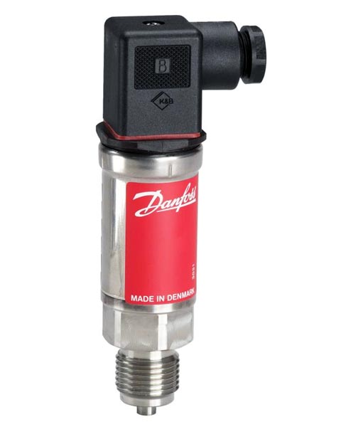
Danfoss MBS 4050, Pressure transmitters with pulse snubber
The heavy duty pressure transmitter MBS 4050 is designed for use in hydraulic applications with severe medium influences like cavitation, liquid hammer or pressure peaks and offers a reliable pressure measurement, even under harsh environmental conditions.
The flexible pressure transmitter programme covers 4-20 mA, 0-5 V, 1-5 V, 1-6 V and 0-10V output signal, absolute and gauge (relative) versions, measuring ranges from 0-1 to 0-600 bar and a wide range of pressure- and electrical connections.
Excellent vibration stability, robust construction, and a high degree of EMC/EMI protection equip the pressure transmitter to meet the most stringent industrial requirements.
- 4 – 20 mA, 0 – 5 V, 1 – 5 V, 1 – 6 V or 0 – 10 V output signal
- Operating temperature -40 to 85° C
- Measuring range 0 – 600 bar
- With integrated pulse-snubber
- For use in harsh industrial environments
- Click for the Danfoss MBS 4050 Technical PDF Literature
- For further information call Ray – CSE’s Danfoss Consultant on 023 8025 5757.
Technical Data
| Media: | Air, gas, liquid |
| Operating temperature: | -40oC to 85oC |
| Wetted parts: | AISI 316L (DIN 17440 – 1.4404) |
| Enclosure: | Plug version : IP65 |
| Electrical connection: | DIN 43650 plug Pg9 |
| Accuracy: | ≤± 0.5% FS (typ.), ≤± 0.8% FS (max.) |
| Supply voltage: | 10 to 30V d.c. |
| Output signal: | 4 to 20mA |
| Process connection: | G1/2A, DIN 16288, with integrated pulse snubber |
| Code No | Weight Kg | Pressure range pe | Pressure Connection |
| 060G3275 | 0.28 | 0 to 250 bar | G1/2″ A (DIN 16288) |
MBS 4050 with integrated pulse snubber is specially suited for hydraulic applications where cavitation, liquid hammer or pressure peaks may occur – influences that often cause a short but extreme excess of the max. working pressure of the transmitter.
The integrated pulse snubber is in principle design as a nozzle mounted in the passage between the measured medium and the pressure sensitive element of the transmitter.
Application – Cavitation, liquid hammer and pressure peaks may occur in hydraulic systems with changes in flow velocity, e.g. fast closing of a valve or pump starts and stops. The problem can occur on the inlet and outlet side of a pump or valve even at rather low operating pressures.
Media condition – Clogging of the nozzle may occur in liquids containing particles. Mounting the transmitter in an upright position minimises the risk of clogging, because the flow into the nozzle is restricted to the start-up period when the dead volume behind the nozzle fills. The media viscosity has only little effect on the response time. Even at viscosities up to 100cSt, the response time will not exceed 4ms.