


 The MS450 manual motor starters covers the range from 15 kW (400 V AC) / 32 A to 22 kW (400 V AC) / 50 A in a width of 55 mm. The MS495 is for the protection of bigger motors up to 55 kW (400 V) / 100 A in a width of 75 mm.
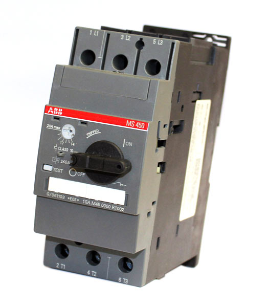
Manual motor starters (MMS) are protection devices for the main circuit. They combine motor control and protection in a single device. MMS are used mainly to switch motors manually ON/OFF and protect them and the installation fuse less against short-circuit, overload and phase failures. Fuse less protection with a manual motor starter saves costs, space and ensures a quick reaction under short-circuit condition, by switching off the motor within milliseconds.
Further features are the build-in disconnect function, temperature compensation, trip-free mechanism and a rotary handle with a clear switch position indication. The manual motor starter is suitable for three and single-phase applications. The handle is lockable to protect against unauthorised changes. Auxiliary contacts, signalling contacts, undervoltage releases, shunt trips, three-phase busbars, power in-feed blocks are available as accessory.
|
Rated operational power 400 V |
Setting range | Short-circuit breaking capacity ICS at 400 V AC |
Rated instantaneous short circuit current setting li |
Type | Order code |
Weight (1 pce) |
| kW | A | kA | A | kg | ||
| MS450 manual motor starter | ||||||
| 15.8 | 28.0 … 40.0 | 25 | 520.00 | MS450-40 | 1SAM450000R1005 | 1.047 |
| 22 | 36.0 … 45.0 | 25 | 585.00 | MS450-45 | 1SAM450000R1006 | 1.039 |
| 22 | 40.0 … 50.0 | 25 | 650.00 | MS450-50 | 1SAM450000R1007 | 1.027 |
| MS495 manual motor starter | ||||||
| 30 | 45.0 … 63.0 | 25 | 819.00 | MS495-63 | 1SAM550000R1007 | 2.247 |
| 37 | 57.0 … 75.0 | 25 | 975.00 | MS495-75 | 1SAM550000R1008 | 2.253 |
| 45 | 70.0 … 90.0 | 25 | 1170.00 | MS495-90 | 1SAM550000R1009 | 2.280 |
| 55 | 80.0 … 100.0 | 25 | 1235.00 | MS495-100 | 1SAM550000R1010 | 2.295 |
Technical Data
| Type | MS450, MS495, MS497 |
| Standards | IEC/EN 60947-2, IEC/EN 60947-4-1, IEC/EN 60947-1 |
| Rated operational voltage Ue | 690 V AC / 450 V DC |
| Rated frequency | 50/60 Hz |
| Trip class | 10 |
| Number of poles | 3 |
| Duty time | 100 % |
| Rated impulse withstand voltage Uimp | 6 kV |
| Rated insulation voltage Ui | 690 V AC |
Short-circuit breaking capacity and back-up fuses
lCS Rated service short-circuit breaking capacity
lCU Rated ultimate short-circuit breaking capacity
ICC Prospective short-circuit current at installation location
| Type | 240 V AC | 400 V AC | 440 V AC | 500 V AC | 690 V AC | ||||||||||
|
ICS kA |
ICU kA |
gG, aM A |
ICS kA |
ICU kA |
gG, aM A |
ICS kA |
ICU kA |
gG, aM A |
ICS kA |
ICU kA |
gG, aM A |
ICS kA |
ICS kA |
gG, aM A |
|
| Short-circuit protection MS450 | |||||||||||||||
| MS450-40 |
No back-up fuse required up to ICC = 100 kA |
25 | 50 | 160 | 15 | 50 | 125 | 5 | 10 | 100 | 2 | 4 | 63 | ||
| MS450-45 | 25 | 50 | 160 | 15 | 50 | 125 | 5 | 10 | 100 | 2 | 4 | 63 | |||
| MS450-50 | 25 | 50 | 160 | 15 | 50 | 125 | 5 | 10 | 100 | 2 | 4 | 80 | |||
|
MS450: No need for back-up fuse in networks with a prospective current of up to 50 kA at 400 V. With an approbiate 160 A type gG fuse the device can be used in a network with a prospective current of up to 100 kA. |
|||||||||||||||
| Short-circuit protection MS495 | |||||||||||||||
| MS495-40 | No back-up fuse required up to ICC = 100 kA | 25 | 50 | 125 | 20 | 50 | 125 | 6 | 12 | 125 | 3 | 6 | 63 | ||
| MS495-50 | 25 | 50 | 125 | 20 | 50 | 125 | 6 | 12 | 125 | 3 | 6 | 80 | |||
| MS495-63 | 25 | 50 | 160 | 20 | 50 | 160 | 6 | 12 | 160 | 3 | 6 | 80 | |||
| MS495-75 | 25 | 50 | 160 | 20 | 50 | 160 | 6 | 8 | 160 | 3 | 5 | 100 | |||
| MS495-90 | 25 | 50 | 160 | 20 | 50 | 160 | 6 | 8 | 160 | 3 | 5 | 125 | |||
| MS495-100 | 25 | 50 | 160 | 20 | 50 | 160 | 6 | 8 | 160 | 3 | 5 | 125 | |||
|
MS495-40: No need for back-up fuse in networks with a prospective current of up to 50 kA at 400 V. With an approbiate 125 A type gG fuse the device can be used in a network with a prospective current of up to 100 kA. MS495-100: No need for back-up fuse in networks with a prospective current of up to 50 kA at 400 V. With an appropriate 160 A type gG fuse the device can be used in a network with a prospective current of up to 100 kA. |
|||||||||||||||
General Technical Data
| Type | MS450 | MS495 | ||
| Pollution degree | 3 | |||
| Phase loss sensitive | Yes | |||
| Ambient air temperature | ||||
| Operation | Open – compensated without derating | -20 … +60 °C | ||
| Open | -20 … +70 °C | |||
| Enclosed | -20 … +35 °C | |||
| Storage | -50 … +80 °C | |||
| Ambient air temperature compensation | Continuous | |||
| Maximum operating altitude permissible | 2000 m | |||
| Resistance to shock acc. to IEC 60068-2-27 | 25 g / 11 ms | – | ||
| Resistance to vibrations acc. to IEC 60068-2-6 | 2 g / 5-150 Hz | |||
| Mounting position | Position 1-6 (optional for single mounting) | |||
| Mounting | DIN-rail 35 mm (EN 60715) | DIN-rail 15 mm / 75 mm (EN 60715) | ||
| Minimum distance to other units same type | Horizontal | 0 mm | 0 mm | |
| Vertical – up to 240 V | – | 50 mm | ||
| Vertical – up to 440 V | – | 70 mm | ||
| Vertical – up to 500 V | – | 110 mm | ||
| Vertical – up to 690 V | – | 150 mm | ||
| Vertical | 50 mm | – | ||
| Minimum distance to electrical conductive board | Horizontal | 10 mm | – | |
| Horizontal – up to 500 V | – | 10 mm | ||
| Horizontal – up to 690 V | – | 30 mm | ||
| Vertical – up to 240 V | – | 50 mm | ||
| Vertical – up to 440 V | – | 70 mm | ||
| Vertical – up to 500 V | – | 110 mm | ||
| Vertical – up to 690 V | – | 150 mm | ||
| Vertical | 50 mm | – | ||
| Degree of protection | Enclosure / terminals | IP20 | ||