


Low Voltage – Control and Power Reeling Cables
Buflex X’Prem Applications
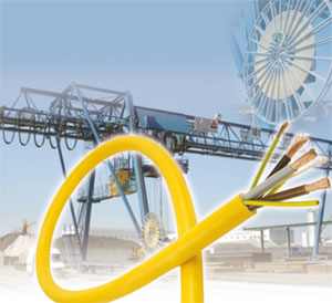
BUFLEX® X’PREM cables with polyurethane sheath are specially designed for reeling application, with high mechanical stresses and sever environmental conditions such as torsion, tension, torque and abrasion.
A strength member has been integrated to increase tensile load, acceleration and speed.
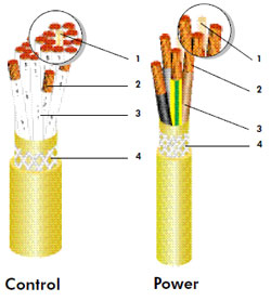
Buflex X’Prem Design
1. Central strength member : Aramid yarns
2. Conductor : Flexible plain copper class 5 IEC 60228
3. Insulation : XLPE
4. Outer Sheath : Double layer with anti-twisting reinforcement PU; Colour: Yellow
Marking
BUFLEX® X’PREM – 0.6/1 kV
Number of cores – cross-section
 NEXANS – week – year
Core Identification
Control: white with printed numbers
Power:
- 4 cores: black – brown – grey – green/yellow (3 earth cores for sizes >25 mm2)
- 5 cores: black – brown – grey – blue – green/ yellow
Standards
Nexans specification
Cable Characteristiscs
Mechanical properties
| Max. tensile load : | 25 N/mm2 of phases copper cross section |
| Bending radii fixed: : | 6 x d mobile: 8 x d s-shape deflection: 20 x d Tests Bending test, torsional test, reeling test Reeling speed up to 150 m/min (for higher speed contact us) |
| Tests | Bending test, torsional test, reeling test |
| Reeling speed | up to 150 m/min (for higher speed contact us) |
| Chemical properties | Oil & Chemicals resistant. For outdoor applications. Moisture, UV and ozone resistance. |
Electrical and Thermal properties |
|
| Nominal voltage | Uo/U : 0.6/1 kV |
| Maximum operating voltage in AC systems | Um : 1.2 kV |
| Test voltage: | |
| – Power | 3.5 kV in AC |
| – Control | 2.5 kV in AC |
| Current rating (A) | – in accordance with IEC 60354-5-52-12 |
| Max. temperature at the conductor : | |
| – in service | + 90 °C |
| – under short-circuit conditions | + 250 °C |
| Max. surface temperature : | |
| – fixed installation | – 40 °C up to + 80 °C |
| – mobile operation | – 30 °C up to + 80 °C |
Cable Specification and Ordering
| Number of cores and nominal cross-section | Outer Diameter | Weight (approx.) | Maximum tensile load | Current Carrying Capacity | ||
| (mm2) | Min. (mm) | Max. (mm) | (kg/km) | (N) | (A) | |
| Power | 4 x 2.5 | 10 | 11.5 | 180 | 250 | 30 |
| 4 G 4 | 11.5 | 13 | 260 | 400 | 40 | |
| 4 G 10 | 15.5 | 17 | 580 | 1000 | 71 | |
| 4 G 16 | 19.5 | 21.5 | 920 | 1600 | 95 | |
| 3 x 25 + 3 G 6 | 23.5 | 25.5 | 1240 | 1960 | 121 | |
| 3 x 35 + 3 G 6 | 27 | 29.5 | 1640 | 2650 | 150 | |
| 3 x 50 + 3 G 10 | 30 | 32.5 | 2240 | 3750 | 182 | |
| 3 x 70 + 3 G 16 | 35 | 37.5 | 3100 | 5250 | 234 | |
| 3 x 95 + 3 G 16 | 39 | 42 | 3890 | 7150 | 283 | |
| 3 x 120 + 3 G 25 | 44 | 47 | 5080 | 9000 | 329 | |
| 3 x 150 + 3 G 25 | 49 | 52.5 | 6160 | 11250 | 375 | |
| 3 x 185 + 3 G 35 | 54.5 | 58.5 | 7680 | 13800 | 428 | |
| 3 x 240 + 3 G 50 | 60.5 | 64.5 | 9870 | 18000 | 511 | |
| 3 x 300 + 3 G 50 | 68.5 | 72.5 | 12300 | 22500 | 555 | |
| 5 G 2.5 | 11 | 12.5 | 220 | 310 | 30 | |
| 5 G 4 | 13 | 14.5 | 320 | 500 | 40 | |
| 5 G 6 | 15 | 16.5 | 450 | 750 | 51 | |
| 5 G 10 | 18 | 20 | 700 | 1250 | 71 | |
| 5 G 16 | 22 | 24 | 1100 | 2000 | 95 | |
| 5 G 25 | 27 | 29.5 | 1550 | 3100 | 121 | |
| 5 G 35 | 31 | 33.5 | 2050 | 4350 | 150 | |
| Control | 7 x 1.5 | 11.5 | 13 | 210 | 260 | 20 |
| 12 x 1.5 | 16 | 17.5 | 330 | 450 | 16 | |
| 18 x 1.5 | 16 | 17.5 | 410 | 670 | 12 | |
| 24 x 1.5 | 19 | 21.5 | 680 | 900 | 10 | |
| 36 x 1.5 | 22 | 24 | 900 | 1350 | 8 | |
| 7 x 2.5 | 12.5 | 14 | 30 | 430 | 28 | |
| 18 x 2.5 | 18.5 | 20.5 | 740 | 1120 | 16 | |
| 24 x 2.5 | 22.5 | 24.5 | 1050 | 1500 | 12 | |
| 42 x 2.5 | 27 | 29.5 | 1500 | 2620 | 8 | |
| 26 x 2.5 + (4 x 2.5)C | 24.5 | 27 | 1260 | 1870 | 11 | |
Current carrying capacities are given for an uncoiled cable laid on the ground, a conductor temperature of 90°C and ambient temperature of 30°C.
Correction factors must be apply for other conditions.
Options
Other composition can be manufactured on request as e.g.
composite cables including power and control cores, screened pairs or optical fibers element.