


 1. Generalities
Copper conductors for flexible handling cables are manufactured in accordance with IEC 60228 DIN VDE 0295 / CENELEC HD 383 and prEN 60228. Nexans uses class 5 and /or class 6 design.
2. Conductor material
Copper (Cu), a nonferrous metal with a density of 8.945 kg/dm3 and a melting point of 1,083 °C is characterized by a high degree of chemical stability and excellent thermal and electrical conductivity.
Mechanical and electrical properties :
– tensile strength 210 to 230 N/mm2
– elongation at break > 40 %
– electrical conductivity > 58.0 m/Ω mm2
(the indicated values are non binding average values)
Class 5 flexible copper conductor for single-core and multi-core cables
| Nominal Cross-section area | Maximum diameter of wires in conductor | Maximum resistance of conductors at 20 oC | ||
| Neans FSC | DIN EN / IEC 60228 | Plain Wires | Metal-coated wires | |
| mm2 | mm | mm | ( Ω / km) | ( Ω / km) |
| 0.5 | 0.191 | 0.21 | 39 | 40.1 |
| 0.75 | 0.191 | 0.21 | 26 | 26.7 |
| 1 | 0.191 | 0.21 | 19.5 | 20 |
| 1.5 | 0.251 | 0.26 | 13.3 | 13.7 |
| 2.5 | 0.251 | 0.26 | 7.98 | 8.21 |
| 4 | 0.301 | 0.31 | 4.95 | 5.09 |
| 6 | 0.301 | 0.31 | 3.3 | 3.39 |
| 10 | 0.396 | 0.41 | 1.91 | 1.95 |
| 16 | 0.396 | 0.41 | 1.21 | 1.24 |
| 25 | 0.396 | 0.41 | 0.78 | 0.795 |
| 35 | 0.396 | 0.41 | 0.554 | 0.565 |
| 50 | 0.396 | 0.41 | 0.386 | 0.393 |
| 70 | 0.396 | 0.51 | 0.272 | 0.277 |
| 95 | 0.396 | 0.51 | 0.206 | 0.21 |
| 120 | 0.396 | 0.51 | 0.161 | 0.21 |
| 150 | 0.396 | 0.51 | 0.129 | 0.132 |
| 185 | 0.396 | 0.51 | 0.106 | 0.108 |
| 240 | 0.396 | 0.51 | 0.0801 | 0.0817 |
| 300 | 0.396 | 0.51 | 0.0641 | 0.0654 |
| 400 | 0.396 | 0.51 | 0.0486 | 0.0495 |
| 500 | 0.396 | 0.61 | 0.0384 | 0.0391 |
| 630 | 0.396 | 0.61 | 0.0287 | 0.0292 |
Class 6 flexible copper conductor for single-core and multi-core cables
| Nominal Cross-sectional area | Maximum diameter of wires in conductor | Maximum resistance of conductors at 20°C | ||
| Nexans FSC | DIN EN /IEC 60228 | Plain wires | Metal-coated wires | |
| (mm2) | (mm) | (mm) | ( Ω / km) | ( Ω / km) |
| 0.5 | 0.148 | 0.16 | 39 | 40.1 |
| 0.75 | 0.148 | 0.16 | 26 | 26.7 |
| 1 | 0.148 | 0.16 | 19.5 | 20 |
| 1.5 | 0.148 | 0.16 | 13.3 | 13.7 |
| 2.5 | 0.148 | 0.16 | 7.98 | 8.21 |
| 4 | 0.148 | 0.16 | 4.95 | 5.09 |
| 6 | 0.191 | 0.21 | 3.3 | 3.39 |
| 10 | 0.21 | 1.91 | 1.95 | |
| 16 | 0.21 | 1.21 | 1.24 | |
| 25 | 0.21 | 0.78 | 0.795 | |
| 35 | 0.21 | 0.554 | 0.565 | |
| 50 | 0.31 | 0.386 | 0.393 | |
| 70 | 0.31 | 0.272 | 0.277 | |
| 95 | 0.31 | 0.206 | 0.21 | |
| 120 | 0.31 | 0.161 | 0.164 | |
| 150 | 0.31 | 0.129 | 0.132 | |
| 185 | 0.41 | 0.106 | 0.108 | |
| 240 | 0.41 | 0.0801 | 0.0817 | |
| 300 | 0.41 | 0.0641 | 0.0654 | |
3. Design and function of stranded flexible conductors
To ensure optimum service life in crane applications, the conductor must be flexible including high bending qualities.
Flexibility is defined as the force required to bend the conductor. The best results can be achieved by subdividing the conductor diameter into several individual strands. Smaller the diameter of the individual wires, higher the flexibility of the conductor.
Individual strands are twisted together to ensure the necessary cohesion within the conductor. When a conductor is bent with a radius r, tensile and compression stresses are created within the conductor, the extent of which depend on r. The tensile forces are most pronounced in the outer margins of the conductor farest away from the bending center m, whereas the compression stress is highest in the marginal area closer to the bending center m.
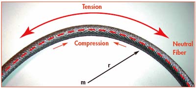
r = bending radius
M= bending centre
A conductor consists of several twisted strands, the individual wires change their position with varying degrees of frequency between bending and compression areas, so that the tensile and compression stress virtually offset each other.
Consequently, such offsetting processes can take place more frequently if the length of lay is shortened. By this way, all handling cables from NEXANS are optimized regarding the best bending qualities and flexibility for reeling and festoon applications.
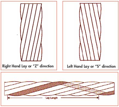
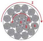
Direction of lay
The stranding of a conductor is clearly defined when the twisting direction of the strand is also defined. The two possible twist directions are usually indicated with the letters S and Z, respectively (regardless of the observer’s position).
Length of lay
The length of lay is defined as the quantifiable twist completed by a strand around the conductor axle, as measured in the axial direction. Frequently, the length of lay is also measured as a multiple of the conductor diameter: e.g. 10 x D.
Bunched wires
This type of conductor is characterized by the fact that the position of individual wires is not clearly defined. Any number of wires can be bundled and twisted – they are bunched. Nexans uses this conductor type in their flexible handling cables only for ≤ 10 mm2.
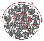
Concentric rope lay conductors
Rope-lay conductors consist of a number of rope-lay elements characterized by regular concentric stranding layers. Within the stranded conductor, the position of each member in relation to its neighbouring members is clearly defined. Rope-lay conductors are characterized by uniform surface and almost roundness.
Its bending stability is high; its shape stays round and circular. For the different applications we find following various rope-lays:
| Rope-lay type |
Equal-lay | Reversed-lay | Cross-lay | ||||||||||||||||||||||||||||||||||||
| Definition | All lay directions in the strand and rope lays are uniform |
The lay directions of the individual layers in the rope-lay conductor alternate. However, the lay direction in the rope lay still corresponds to that of the respective strand layer |
Alternate lay directions in successive layers of the strand and opposite lay direction of rope-lays and stranded layers. |
||||||||||||||||||||||||||||||||||||
 |
 |
 |
|||||||||||||||||||||||||||||||||||||
| Design |
|
|
|
||||||||||||||||||||||||||||||||||||
| Characteristics |
|
|
|
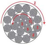
In the case of a 3 layer design, the 3rd layer is Z stranded.
The inner layers are in the same direction as shown in the drawings.